
Chapter 10
|
|
Chapter 10 |
| Link to Book Table of Contents | Chapter Contents Shown Below |
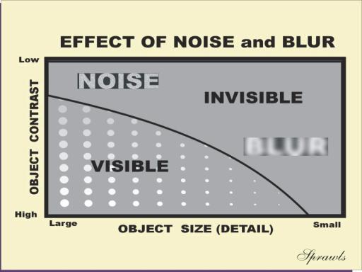
Two characteristics of the MR image that reduce the visibility of anatomical structures and objects within the body are blurring and visual noise. These were introduced in Chapter 1 as image quality characteristics. Both image blurring and visual noise are undesirable characteristics that collectively reduce the overall quality of an image and the objects in the image as illustrated in Figures 1-6 and 1-7. In an image, the combined effects of blur and noise produce a “curtain of invisibility” that extends over some objects based on object characteristics. This is shown in Figure 10-1, where we see objects arranged according to two characteristics. In the horizontal direction, the objects are arranged according to size. Decreasing object size corresponds to increasing detail.
|
Figure 10-1. The impact of image noise and blurring
on object visibility. Noise reduces visibility of low contrast objects.
Blur reduces visibility of small objects. |
 |
In
the vertical direction, the objects are arranged according to their contrast.
The object in the lower left is both large and has a high level of contrast.
This is the object that would be most visible under a variety of imaging
conditions. The object that is always the most difficult to see is the small,
low contrast object, which in Figure 10-1 would be located in the upper right
corner.
In every imaging procedure we can assume that some potential objects
within the body will not be visible because of the blurring and noise in the
image. This loss of visibility is represented by the “curtain” or area of
invisibility indicated in Figure 10-1. The location of the boundary between the
visible and invisible objects, often referred to as a contrast-detail curve,
is determined by the amount of blurring and noise associated with a specific
imaging procedure. In general, blurring reduces the visibility of anatomical
detail or other small objects that are located in the lower right region. Visual
noise reduces the visibility of low contrast objects located in the upper left
region.
The imaging protocol determines the boundary of visibility by altering
the amount of blurring and noise. These two characteristics are determined by
the combination of many adjustable imaging factors. It is a complex process
because the factors that affect visibility of detail (blurring) also affect
noise, but in the opposite direction. As we will see when a protocol is changed
to improve visibility of detail, the noise is increased. Another point to
consider is that several of the factors that have an effect on both image detail
and noise also affect image acquisition time, which will be discussed in Chapter
11. Therefore, when formulating an imaging protocol one must consider the
multiple effects of the imaging factors and then select factor values that
provide an appropriate compromise and an optimized acquisition for a specific
clinical study with respect to detail (blurring), noise, and acquisition speed.
We will now consider the many factors that have an effect on the
characteristics of image detail and noise.
The
ability of a magnetic resonance image to show detail is determined primarily by
the size of the tissue voxels and corresponding image pixels. Pixel size can be
changed without major tradeoffs. However, as we are about to observe, there are
significant effects of changing voxel size that must be considered. The real
challenge is selecting a voxel size that is optimum for a specific clinical
procedure.
In principle, all structures within an individual voxel are blurred
together and represented by the signal intensity representing that voxel. It is
not possible to see details within a voxel, just the voxel itself. When we view
an MR image, we are actually looking at an image of a matrix, or array, of the
voxels. We usually do not see the individual voxels because they are so small
and they might be interpolated into even smaller image pixels. However, even if
we do not see the individual voxels, their size determines the anatomical detail
that we can see. The amount of image blurring is determined by the dimensions of
the individual voxels.
Three basic imaging factors determine the dimensions of a tissue voxel, as illustrated in Figure 10-2.
| Figure 10-2. Voxel size and detail in MR images is determined by the values selected for the three protocol factors: FOV, matrix size, and slice thickness. |
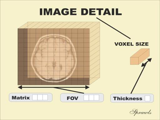 |
The
dimension of a voxel in the plan of the image is determined by the ratio of the
field of view (FOV) and the size of the matrix. Both of these factors can be
used to adjust image detail. The thickness of the slice is a factor in voxel
signal intensity.
The selection of the FOV is determined primarily by the size of the body
part being imaged. One problem that can occur is the appearance of foldover
artifacts when the FOV is smaller than the actual body section. However,
there are artifact suppression techniques that can be used to reduce this
foldover problem, as described in Chapter 14. The maximum useful FOV is usually
limited by the dimensions and characteristics of the RF coil. The important
thing to remember is that smaller image FOVs and smaller voxels produce better
visibility of detail.
Matrix size refers to the number of voxels in the rows or columns of the
matrix. The matrix size is a protocol factor selected by the operator before the
imaging procedure. Typical matrix dimensions are in the range of 128 to 512 mm.
Random
RF energy can be generated by thermal activity within electrical conductors and
circuit components of the receiving system. In principle, the patient’s body is
a component of the RF receiving system. Because of its mass, it becomes the most
significant source of image noise in most imaging procedures. The specific noise
source is the tissue contained within the sensitive FOV of the RF receiver
coils. Some noise might be generated within the receiver coils or other
electronics, but it is usually much less than the noise from the patient’s body.
Many devices in the environment produce RF noise or signals that can
interfere with MRI. These include radio and TV transmitters, electrosurgery
units, fluorescent lights, and computing equipment. All MR units are installed
with an RF shield, as described in Chapter 2, to reduce the interference from
these external sources. External interference is not usually a problem with a
properly shielded unit. When it does occur, it generally appears as an image
artifact rather than the conventional random noise pattern.
Signal-To-Noise Considerations
Image
quality is not dependent on the absolute intensity of the noise energy but
rather the amount of noise energy in relation to the image signal intensity.
Image quality increases in proportion to the signal-to-noise ratio. When the
intensity of the RF noise is low in proportion to the intensity of the image
signal, the noise has a low visibility. In situations where the signals are
relatively weak, the noise becomes much more visible. The principle is
essentially the same as with conventional TV reception. When a strong signal is
received, image noise (snow) is generally not visible; when one attempts to tune
in to a weak TV signal from a distant station, the noise (noise) becomes
significant.
In MRI, the loss of visibility resulting from the noise can be reduced by either reducing the noise intensity or increasing the intensity of the signals. This is illustrated in Figure 10-3.
| Figure 10-3. Factors that affect the signal-to-noise ratios in MR images |
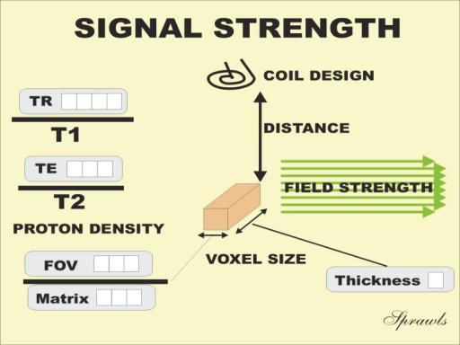 |
Let
us now see how this can be achieved.
One of
the major factors that affects signal strength is the volume of the individual
voxels. The signal intensity is proportional to the total number of protons
contained within a voxel. Large voxels, that contain more protons, emit stronger
signals and result in less image noise. Unfortunately, as we have just
discovered, large voxels reduce image detail. Therefore, when the factors for an
imaging procedure are being selected, this compromise between signal-to-noise
ratio and image detail must be considered. The major reason for imaging
relatively thick slices is to increase the voxel signal intensity and it also
allows shorter TE values.
The
strength of the RF signal from an individual voxel generally increases in
proportion to the square of the magnetic field strength. However, the amount of
noise picked up from the patient’s body often increases with field strength
because of adjustments in the bandwidth factor for the higher fields. This is
described in Chapter 14. Because of differences in system design, no one precise
relationship between signal-to-noise ratio and magnetic field strength applies
to all systems. In general, MRI systems operating at relatively high field
strengths produce images with higher signal-to-noise ratios than images produced
at lower field strengths, when all other factors are equal.
Signal
intensity, and the signal-to-noise ratio, depend to some extent on the magnetic
characteristics of the tissue being imaged. For a specific set of imaging
factors, the tissue characteristics that enhance the signal-to-noise
relationship are high magnetic nuclei (proton) concentration, short T1, and long
T2. The primary limitation in imaging nuclei other than hydrogen (protons) is
the low tissue concentration and the resulting low signal intensity.
Repetition time (TR) and echo time (TE) are the factors used to control contrast
in most imaging methods. We have observed that these two factors also control
signal intensity. This must be taken into consideration when selecting the
factors for a specific imaging procedure.
When a short TR is used to obtain a T1weighted image, the longitudinal
magnetization does not have the opportunity to approach its maximum and produce
high signal intensity. In this case, some signal strength must be sacrificed to
gain a specific type of image contrast. Also, when TR is reduced to decrease
image acquisition time, image noise can become the limiting factor.
When long TE values are used, the transverse magnetization and the
resulting signal it produces can decay to very low values. This causes the
images to display more noise.
RF Coils
The most
direct control over the amount of noise energy picked from the patient’s body is
achieved by selecting appropriate characteristics of the RF receiver coil. In
principle, noise is reduced by decreasing the amount of tissue within the
sensitive region of the coil. Most imaging systems are equipped with
interchangeable coils. These include a body coil, a head coil, and a set of
surface coils as shown in Figure 10-4.
|
Figure 10-4. Both the amount of noise and the
intensity of the signal received depend on the RF receiving coils. The
body coil picks up the most noise and the weakest signal, resulting in
the highest noise level in the image. |
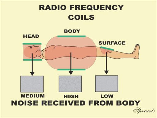 |
The body
coil is the largest coil and usually contains a major part of the patient’s
tissue within its sensitive region. Therefore, body coils pick up the greatest
amount of noise. Also, the distance between the coil and the tissue voxels is
greater than in other types of coils. This reduces the intensity of the signals
actually received by the coil. Because of this combination of low signal
intensity and higher noise pickup, body coils generally produce a lower
signal-to-noise ratio than the other coil types.
In comparison to body coils, head coils are both closer to the imaged
tissue and generally contain a smaller total volume of tissue within their
sensitive region. Because of the increased signal-to-noise characteristic of
head coils, relatively small voxels can be used to obtain a better image detail.
The surface coil provides the highest signal-to-noise ratio of the three
coil types. Because of its small size, it has a limited sensitive region and
picks up less noise from the tissue. When it is placed on or near the surface of
the patient, it is usually quite close to the voxels and picks up a stronger
signal than the other coil types. The compromise with surface coils is that
their limited sensitive region restricts the useful FOV, and the sensitivity of
the coil is not uniform within the imaged area. This non-uniformity results in
very intense signals from tissue near the surface and a significant decrease in
signal intensity with increasing depth. The relatively high signal-to-noise
ratio obtained with surface coils can be traded for increased image detail by
using smaller voxels.
Bandwidth is the range of frequencies (RF) that the receiver is set to receive
and is an adjustable protocol factor. It has a significant effect on the amount
of noise picked up. This is because the noise is distributed over a wide range
of frequencies, whereas the signal is confined to a relatively narrow frequency
range. Therefore, when the bandwidth is increased, more noise enters the
receiver. The obvious question is: Why increase bandwidth? One reason is that a
wider bandwidth reduces the chemical shift artifact that will be described in
Chapter 14. Also, wider bandwidths are the result of short signal sampling, or
“picture snapping” times that are useful in some applications.
One of the most direct methods used to control the signal-to-noise characteristics of MR images is the process of averaging two or more signal acquisitions. In principle, each basic imaging cycle (phase-encoding step) is repeated several times and the resulting signals are averaged to form the final image as illustrated in Figure 10-5.
|
Figure 10-5. an mage with reduced noise is created by averaging the signals from four acquisitions. |
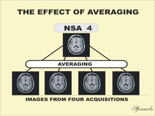 |
The
averaging process tends to reduce the noise level because of its statistical
fluctuation nature, from one cycle to another. You can think of it as acquiring
four images by repeating the basic acquisition four times. Then the signal
intensities in each pixel position in the four images are averaged to produce an
intensity value for the new averaged image.
The disadvantage of averaging is that it increases the total image
acquisition time in proportion to the number of cycle repetitions or number of
signals averaged (NSA). The NSA is one of the protocol factors set by the
operator. Typical values are 1 (no averaging), 2, or 4, depending on the amount
of noise reduction required. The general relationship is that the NSA must be
increased by a factor of 4 to improve the signal-to-noise ratio by a factor of
2. The signal-to-noise ratio is proportional to the square root of the NSA.
Sometimes the noise contribution from independent acquisitions adds; sometimes
it cancels. Since the signals always add, adding or averaging independently
acquired images improves the signal-to-noise ratio.
Parallel imaging is a technique
that is useful for reducing acquisition time.
The signals are acquired with a set of coils in a phased-array
configuration. Making use of the
geometric sensitivity of each coil within the array some degree of anatomical
spatial information is obtained and used in the image reconstruction process.
This makes it possible to reduce the number of phase-encoding gradient
cycles and the associated acquisition time.
Mind Map Summary
Image Detail and Noise
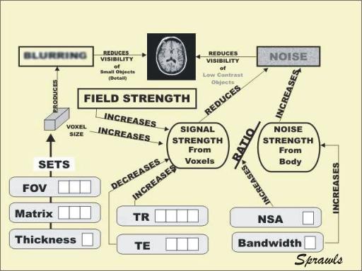
The level of noise that appears in an image depends on the relationship
(ratio) of the signal strength from the individual voxels and the noise strength
coming from a region of the patient’s body. The visible noise is reduced by
increasing signal strength. This can be done by increasing the magnetic field
strength, increasing voxel size, increasing TR, and decreasing TE. The field
strength is a design characteristic and cannot be changed by the operator.
Increasing voxel size to decrease noise has the adverse effect of also
increasing blurring. Voxel sizes must be chosen to provide an appropriate
balance between blurring and noise.
The noise strength picked up from the patient’s body is determined by the
mass of tissue contained within the sensitive pickup region of the RF coils.
Surface coils that cover a relatively small anatomical region and are also close
to the signal source (voxels) produce a high signal-to-noise relationship that
results in lower image noise. The RF receiver bandwidth can be adjusted to block
some of the noise energy from being received. However, decreasing the bandwidth
to reduce noise has the adverse effect of increasing the chemical shift
artifact.
Signal averaging is a useful technique for reducing noise but has the
adverse effect of increasing acquisition time.