|
|

Digital Radiography
|
Outline |
Mind Map |
|
|
Digital Radiography
|
Outline |
Mind Map |
To begin study of the module,
CLICK
HERE.
 Digital
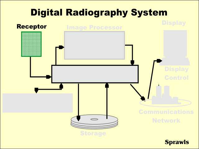
radiography is performed by a system consisting of the following
functional components: Digital
radiography is performed by a system consisting of the following
functional components:
In this and other modules, each of these components will be considered and detail. At this time we will briefly introduce the various components. |
 The
digital receptor is the device that intercepts the x-ray beam after it
has passed through the patients body and produces an image in digital
form, that is, a matrix of pixels, each with a numerical value. The
digital receptor is the device that intercepts the x-ray beam after it
has passed through the patients body and produces an image in digital
form, that is, a matrix of pixels, each with a numerical value.This replaces the cassette containing intensifying screens and film that is used in non-digital, film-screen radiography. As we will soon see, there are several different types of digital radiography receptors. |
 Image
management is a function performed by the computer system associated
with the digital radiography process. Image
management is a function performed by the computer system associated
with the digital radiography process.These functions consist of controlling the movement of the images among the other components and associating other data and information with the images. Some of these functions might be performed by the computer component of a specific digital radiography device or by a more extensive Digital Image Management System (DIMS) that serves many imaging devices within a facility. Note: it is not unusual for the DIMS to be referred to by an older, and somewhat less appropriate name, PACS (Picture Archiving and Communications System). |
 The
Patient Information System, perhaps known as the Radiology Information
System (RIS), is an adjunct to the basic digital radiography system.
Through the interface, information such as patient ID, scheduling,
actual procedures performed, etc is transferred. The
Patient Information System, perhaps known as the Radiology Information
System (RIS), is an adjunct to the basic digital radiography system.
Through the interface, information such as patient ID, scheduling,
actual procedures performed, etc is transferred. |
 One
of the major advantages of digital radiography is the ability to process
the images after they are recorded. One
of the major advantages of digital radiography is the ability to process
the images after they are recorded.Various forms of digital processing can be used to change the characteristics of the digital images. For digital radiographs the ability to change and optimize the contrast is of great value. It is also possible to use digital processing to enhance visibility of detail in some radiographs. The various processing methods are explored in much more detail in another module. |
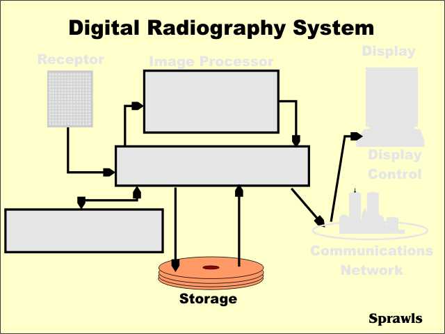 Digital
radiographs, and other digital medical images, are stored as digital
data. Digital
radiographs, and other digital medical images, are stored as digital
data.Advantages (compared to images recorded on film) include:
The digital image storage methods and process is explored in more detail in another module. |
 Another
advantage of digital images is the ability to transfer them from one
location to another very rapidly. Another
advantage of digital images is the ability to transfer them from one
location to another very rapidly.This can be:
The total network available for transferring digital images is made up of a variety of integrated systems as will be described in another module. |
 Compared
to radiographs recorded and displayed on film, i.e. "softcopy", there
are advantages of "softcopy" displays. Compared
to radiographs recorded and displayed on film, i.e. "softcopy", there
are advantages of "softcopy" displays.One major advantage is the ability of the viewer to adjust and optimize image characteristics such as contrast. Other advantages include the ability to zoom, compare multiple images, and perform a variety of analytical functions while viewing the images. |
 We
can think of the direct digital radiographic receptor as "a digital
x-ray camera". We
can think of the direct digital radiographic receptor as "a digital
x-ray camera".The receptor is in the form of a matrix of many individual pixel elements. They are based on a combination of several different technologies, but all have this common characteristic: when the pixel area is exposed by the x-ray beam (after passing through the patient's body), the x-ray photons are absorbed and the energy produces an electrical signal. This signal is a form of analog data that is then converted into a digital number and stored as one pixel in the image. |
 We
can think of the stimualible phosphor receptor as being like a
conventional radiographic intensifying screen in that it absorbs the
x-ray photons and and then produces light. We
can think of the stimualible phosphor receptor as being like a
conventional radiographic intensifying screen in that it absorbs the
x-ray photons and and then produces light.The difference is that there is a delay between the x-ray exposure and the production of the light. This is how it works:
|
 As
the surface of the stimualible phosphor screen is scanned by the laser
beam, the analog data representing the brightness of the light at each
point is converted into digital values for each pixel and stored in the
computer memory as a digital image. As
the surface of the stimualible phosphor screen is scanned by the laser
beam, the analog data representing the brightness of the light at each
point is converted into digital values for each pixel and stored in the
computer memory as a digital image. |
 One
of the significant characteristics of most digital radiographic
receptors is that they have a wide dynamic range. One
of the significant characteristics of most digital radiographic
receptors is that they have a wide dynamic range.What that means is that the receptors respond to x-ray exposure and produce digital data over a wide range of x-ray exposure values as illustrated here. There are distinct advantages of this characteristic as we will see later. We can appreciate this characteristic by comparing it to that of film in the next step. |
|
The latitude (or dynamic range) is the range of receptor exposures over which an image and contrast will be formed. The relationship between receptor exposure and the resulting film density is usually described by the film characteristic (or H & D) curve as we see here. The latitude (or dynamic range) is associated with that part of the curve where there is some slope and contrast will be formed. In the region of the toe of the curve, there is no significant contrast formed, and this corresponds to under-exposed areas within an image. In the region of the shoulder of the curve there is no significant contrast formed and this corresponds to areas of overexposure. This somewhat limited latitude or dynamic range is a characteristic of film because of the way images are formed with the silver halide crystals. Digital receptors do not have this limitation. |
|
X-ray images and image contrast are formed as the x-ray beam passes through the body and experiences different levels of attenuation through the various anatomical regions. In the example of the chest, the low-density lung areas produce a relatively high exposure to the receptor and dark areas in the image. The more dense areas ,like the spine and below the diaphragm, produce relatively low exposure to the receptor and light areas in the image. The histogram, as we see here, shows the amount of image area (in a digital image this is the number of pixels) that receives the different levels of exposure that forms the image. At this time our primary interest is in the range of exposures (width of the histogram) that reaches the receptor. |
 One
of the challenges in doing film radiography is to get the range of
exposures produce by the body (as described by the exposure histogram)
fitted into the latitude or dynamic range of the film. One
of the challenges in doing film radiography is to get the range of
exposures produce by the body (as described by the exposure histogram)
fitted into the latitude or dynamic range of the film.
If the exposure falls outside of the latitude, there will be little or no image contrast formed. There are generally two conditions that contribute to receptor exposure outside of a film's latitude:
Using a film with a wide latitude, as is usually done for chest imaging, can reduce this problem but the tradeoff is that a film with a wide latitude generally produces less contrast than a so-called contrast film. |
 Here
we see one of the advantages of a digital receptor that has a wide
dynamic range. Here
we see one of the advantages of a digital receptor that has a wide
dynamic range.Even when there is a wide exposure range coming from the body (wide histogram) and exposures at different levels (because of exposure errors), we see that they still fit within the wide dynamic range of the digital receptor. This means that good image contrast can be formed over a wide range of exposures. |
 In
a digital image contrast is represented by the different pixel values. In
a digital image contrast is represented by the different pixel values.A typical digital radiographic receptor has a linear relationship between exposure and the resulting pixel value as shown here. We have also seen that this relationship extends over a relatively wide range of exposures to produce the wide dynamic range. This can be contrasted with the non-linear (curved) relationship between exposure and density, or image brightness, for film. As we have just seen, film also has a very limited latitude or "working range" of exposures. |
 The
wide dynamic range and linear response of the typical digital receptor
is like a "two-edged sword". The
wide dynamic range and linear response of the typical digital receptor
is like a "two-edged sword".The advantage is that a wide range of exposures, and exposure errors, will still produce good image contrast. That is, the loss of contrast with exposure error is not a limiting factor as it is with film. So, what is the problem? It is that while images can be produced throughout the range (as far as contrast is concerned) there are two potential problems as we see here. Even though images with good contrast can be produced with relatively low exposures, they will have a high level of quantum noise. We recall from other modules that the level of image (quantum) noise depends on the exposure to the receptor. When a low exposure is used, the result can be excessive image noise. The other problem is that excessively high and unnecessary exposures can be used to form images. While these images will have good quality (low noise) there will be unnecessary exposure to the patient. This problem does not exist with film radiography because the increased exposure will result in a visibly overexposed film. In general, for a radiographic procedure there is an optimum exposure that produces a good balance between image noise and patient exposure. The challenge to the technologist is to make sure that the technique factors are set to produce this optimum exposure. |
 As
we have just observed, one of the challenges with digital radiography is
knowing when the receptor is correctly and optimally exposed. It is not
like film radiography where under and over exposures are obvious. As
we have just observed, one of the challenges with digital radiography is
knowing when the receptor is correctly and optimally exposed. It is not
like film radiography where under and over exposures are obvious.Different digital radiography systems might not do it the same way, but a typical approach is for the equipment to calculate and display on the image the exposure information. This is displayed as an "S" number. The displayed value generally indicates the calculated SPEED of the receptor that would match the actual exposure used. A low exposure would result in a high calculated S number (like S=1000) and a high exposure would produce low S numbers (like S=50). The staff should determine what is the appropriate range of S values to be used and then monitor the values to insure the exposures are optimum. The optimum S numbers might be different for different digital radiographic systems and also depend on the specific clinical procedure. |
 Like
all medical images, digital radiographs have the five specific quality
characteristics as we see here . Like
all medical images, digital radiographs have the five specific quality
characteristics as we see here .We will now see how three of these, contrast, detail, and noise are effected by the characteristics and operation of the digital system. |
 The
contrast sensitivity of a digital radiographic procedure and the image
contrast depend on several factors. The
contrast sensitivity of a digital radiographic procedure and the image
contrast depend on several factors.Two of these, the x-ray beam spectrum and the effects of scattered radiation are similar to film radiography. What is different, and generally an advantage, with digital radiography is the ability to adjust and optimize the contrast after the image has been recorded. This usually occurs through the digital processing of the image and then the adjustment of the window when the image is being viewed. The details of image processing and windowing are explored in another module. |
 As
in all medical images, visibility of detail is reduced and limited by
the blurring that occurs at different stages of the imaging process as
we see here. As
in all medical images, visibility of detail is reduced and limited by
the blurring that occurs at different stages of the imaging process as
we see here.What is common to both digital and film radiography are three sources of blurring:
What is specific to digital radiography is that additional blurring is introduced by dividing the image into pixels. Each pixel is actually a blur. As we have already observed in other modules, the size of a pixel (amount of blurring) is the ratio of the field of view (image size relative to the anatomy) and the matrix size. Pixel size is a factor that must be considered because it limits detail in the images. There is at least one form of digital image processing that can be used to increase visibility of detail and it will be described in another module. |
 The
most predominant source of noise in digital radiography is generally the
quantum noise associated with the random distribution of the x-ray
photons received by the image receptor. The
most predominant source of noise in digital radiography is generally the
quantum noise associated with the random distribution of the x-ray
photons received by the image receptor.As we have just observed, the level of noise depends on the amount of receptor exposure used to produce an image. With digital radiography it can be adjusted over a rather wide range because of the wide dynamic range of the typical digital receptor. The noise is controlled by using the appropriate exposure factors. |
|
The
digital radiography system consist of a variety of functional components
interacting to provide all of the advantages of digital radiography. There are specific features of the digital radiography process that affect the characteristics and quality of the images. This must be considered and adjusted to obtain optimum image quality. To return to the beginning, |
|
To return to the beginning,
|
 Radiographic
film has a somewhat limited dynamic range which is generally referred to
as the film latitude.
Radiographic
film has a somewhat limited dynamic range which is generally referred to
as the film latitude. Before
we proceed with exploring the characteristics of digital receptors,
let's develop the concept of the exposure histogram as we see here.
Before
we proceed with exploring the characteristics of digital receptors,
let's develop the concept of the exposure histogram as we see here.